")
")
IO-Link Device Software
To implement an IO-Link device TMG offers the IO-Link Device Stack, the IO-Link Device Stack Extensions and IO-Link Device Firmware Update. The Device Stack implements the IO-Link communication up to the Application Layer Interface. The IO-Link Device Stack Extensions handle the IO-Link application functions such as device replacement without a tool. The IO-Link device firmware update is required if the firmware of the IO-Link device is to be updated using a standardized mechanism.
IO-Link Device Stack
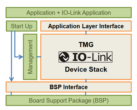
TMG TE's IO-Link device stack is used by the leading device manufacturers and referenced by the leading semiconductor manufacturers. Our software is characterized by its easy portability with very small memory requirements. The consistent separation of hardware customization and protocol stack allows the use with virtually all microcontrollers and all IO-Link transceivers.
- Compliant with the latest IO-Link specification
- Created in ANSI-C 99
- Supports all IO-Link functionality
- Backward compatibility for operation on V1.0 masters
- Support of all types of telegrams
- Device compatibility (support of multiple device IDs in one device)
- Consistent separation of protocol stack and hardware adaptation
- Consistent process data exchange through alternating buffers
- Synchronization of the device software to the process data or communication cycle possible
- Simple adaptation to the specific application in each case using a configuration file
- Does not require an operating system
- Program code: approx. 3,5 kByte
- Depending on microcontroller and compiler
- RAM: approx. 0,5 kByte
- HW Timer: 1 x 8Bit, better 16Bit Timer
- UART: Rx and Tx (at least Rx interrupt, better also Tx interrupt)
- Transmit Enable: GPIO
- Wakeup: 1x interrupt input
- Depending on the transceiver additionally SPI or I²C for configuration and diagnostics, or alternatively to UART SPI for communication at transceivers with frame handler
- Source code in ANSI C99
- PDF documentation
- Sample hardware customization
- Sample application
- The sample application for the IO-Link device stack shows the basic use of the stack with process data, read/write requests and events. However, it does not implement the application functions above the application layer interface. These are implemented conveniently and simply by the IO-Link device stack extensions.
IO-Link Device Stack Extensions
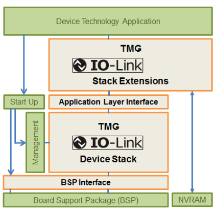
Above the actual communication stack (application layer interface, layer 7), IO-Link from version 1.1 specifies some functions that make the application of the IO-Link devices easier and more valuable for the user. These functions are part of the application and, with a few exceptions, are mandatory. These functions are implemented by the IO-Link Device Stack Extensions.
We have done a very large number of integrations with the Stack Extensions, creating a "best practice" solution that meets virtually all requirements from very simple to very complex IO-Link devices.
The IO-Link software and the implementation of the functionality described in the IODD in the device firmware is child's play with the IO-Link Device Stack and the IO-Link Device Stack Extensions. Here, more is configured than programmed. This saves a lot of time in development and reduces the development risk.
A sample application with IODD and simulation of process data makes it easier to get started and is used for easy commissioning of the hardware platform with IO-Link.
- The Parameter Manager manages all implemented parameters and generates error codes if access rights fail, the length of parameters is not correct and access to non-implemented addresses (index / subindex) is denied.
- This functionality is mandatory
- Enables device replacement without a tool. The IO-Link master provides memory to save the parameters of the device. A state machine including error handling must be implemented. For example, a rollback must occur if the transfer is not successful or results in an inconsistent state. This is also the reason for the double RAM requirement for the RW variables.
- The functionality is mandatory if at least one parameter must be transferred when replacing the device. It is permissible to implement a substitute solution such as a memory card. The substitute solution must work with any standard-compliant IO-Link master. Except in very special cases such as an image recognition system with more memory requirements than the masters provide (2kByte), we do not recommend such a solution, as it is very special and deviates from the expected and usual behavior for the user.
- Note: Data Storage has nothing to do with saving the parameters in the non-volatile memory. This is always additionally necessary regardless of this.
- Automatically stores parameters in non-volatile memory. Double storage for zero voltage safety and CRC protection are supported.
- The transfer of parameters is encapsulated with commands. During the transmission of the parameter block, the dependencies of the variables among each other are not checked. After the block transfer, the device checks the consistency of all parameters. In case of an error, a rollback is performed. This functionality is used to prevent deadlocks during parameter transfer in case of dependencies.
- The functionality is mandatory with the Common Profile. This is highly recommended for all IO-Link devices, which means it is mandatory unless there are compelling reasons not to implement it. However, it would then have to be described in the manufacturer's declaration and the user documentation.
- Device Access Locks is the standard mechanism with which the user can lock and unlock the local parameterization or enable and disable a local operation (e.g. display).
- The functionality is mandatory if there are local operating options.
- Standard diagnostics, where the device status is displayed as a compressed status and as a detailed device status in the form of a list of all pending events.
- The functionality is mandatory with the Common profile.
- The IO-Link device stack allows events to be transmitted, but there are rules for the application to avoid a flood of events and for the behavior when several events occur simultaneously. This is solved by the event dispatcher.
- The functionality is mandatory.
- At the request of large users, a profile was defined that specifies the minimum requirements for IO-Link devices for good system consistency. This profile is mandatory when implementing device profiles such as the Smart Sensor Profile, Firmware Update and IO-Link Safety, but must also be implemented for all IO-Link devices that do not follow a specific device profile, except in special cases.
- Often settings must be made at the end of the production process and stored in the device, such as: serial number, calibration data, or device identification, presettings, etc., if, for example, the same printed circuit board is used for different products.
- These parameters are not visible to the user and are protected by a password and a hiding mechanism. The easiest way to implement such functionality is to use the IO-Link mechanism.
- The functionality is additional to the IO-Link standard and was specified and implemented by TMG TE. Most of our customers use this functionality.
- Note: Some of our customers use the TMG USB-IO-Link Master V2 to perform the production test and settings. We provide libraries for Windows to integrate the TMG USB-IO-Link Master into the test environment.
- Created in ANSI-C 99
- Easily portable to any platform
- Consistent separation of logical and hardware-dependent parts
- Hardware abstraction interface for addressing the non-volatile memory
- Does not require an operating system
- Program code: approx. 6,5 kByte
- Depending on microcontroller and compiler
- RAM
- depending on the variables to implement
- Length of read/write variables x 2 + minor overhead
- Non volatile memory
- Note: Program Flash is mostly not usable due to data retention and freezing of program execution while deleting Flash segments.
- For 0-voltage-safe implementation Memory requirement as for RAM
- Possible solutions:
- Preferred solutions: EEPROM, Data Flash or FRAM
- Also already realized: For microcontrollers with large flash and RAM: SW completely loaded into RAM and executed there. By changing the memory locations in the flash, the write cycles are reduced so far that also with the program flash enough memory cycles are available.
- Source code in ANSI C99
- PDF documentation
- Template for hardware customization for non-volatile memory
- Sample application with simulated process data
- IODD for the sample application
IO-Link Device Firmware Update
The complexity of the firmware in IO-Link devices is increasing. Accordingly, the ability to update the firmware for new functions or bug fixes is becoming increasingly important. The IO-Link community has therefore specified a standardized solution for this requirement.
The solution consists of a bootloader, an IO-Link sample application with the IO-Link Firmware Update Profile including IODD and the TMG IO-Link Firmware Packager.
The solution with a bootloader ensures 0 voltage security. If something goes wrong during the update, the bootloader functionality is still available and the FW download can be attempted again. The bootloader requires the IO-Link device stack, since the IO-Link protocol is used for the transfer. In bootloader mode, the new firmware is transferred using the Binary Large Object Profile (BLOB).
In the actual IO-Link software (production firmware), some functionalities specific to the FW Update Profile are implemented, such as hardware identification and the change to boot mode. This is also described accordingly in the IODD.
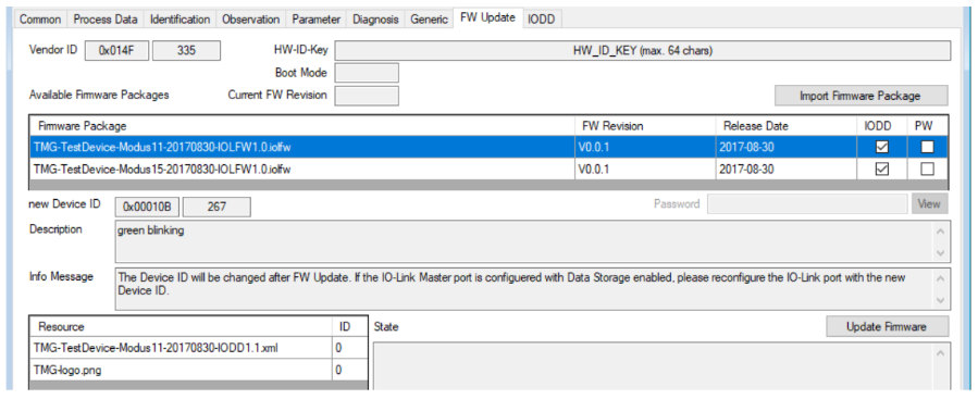
So that any IO-Link-compliant tools can process the firmware for the update, it must be provided accordingly. For this purpose, the firmware is packaged as a binary file with a description file (meta file) and, if necessary, with the new IODD required for this firmware in a firmware package. This is done by the TMG IO-Link Device Firmware Packager included in the scope of delivery. In addition to the mandatory functions for the FW Update Profile, encryption (firmware packager) and decryption (bootloader) with the RC4 algorithm are also included. Thus we take into account the protection of your know-how and unauthorized manipulation.
The IO-Link device firmware update functionality is supported by our IO-Link Device Tool V5.1 in the Standard and Professional Edition as well as by the Windows DLL available for our TMG USB IO-Link Master V2. Thus we offer the complete tool chain from development to application.
- Implementation according to IO-Link Profile BLOB Transfer & Firmware Update V1.1 (09/2019)
- Created in ANSI-C 99
- TMG IO-Link Firmware Update Packager Tool
- based on IODD
- automatically takes over the configuration from the IODD
- Creates the Meta Data File and calculates the CRC
- Can encrypt firmware with RC4
- Can package the "new" IODD in the firmware package
- Creates the firmware package * .iolfw
- Command line control possible
- Can thus be integrated into the firmware generation process
- Supported by IO-Link Device Tool V5.1 SE, PE and TS
- Import of firmware update packages
- into the internal database of the IO-Link Device Tool V5.1
- Automatic adoption of the new IODD
- Firmware updates for IO-Link devices
- Possible with and without IODD
- Approx. 8 kByte flash are required for the boot loader.
- We recommend reserving the next largest number of flash segments for the boot loader.
- Bootloader:
- Source code in ANSI C99
- PDF documentation
- Sample hardware customization
- Production software
- Sample project based on our IO-Link device stack and the IO-Link stack extensions with associated IODD
- IODD with IO-Link Device Firmware Update Profile
- TMG IO-Link Device Firmware Packager